Diffractive Effects
Diffraction occurs whenever a portion of a wavefront is obstructed by some opaque object. Close
examination of a shadow under a bright source will reveal that it is made up of finely spaced bright and dark
regions. In this case, light appears not to be propagating in a straight line; the obstacle alters the amplitude
or phase of the light waves such that the regions of the wavefront that propagate beyond the obstacle will
interfere with each other. It is crucial to remember that there is no physical difference between
interference and diffraction. In general interference concerns situations where only a few
waves are interfering, while diffraction concerns a large number of interfering waves. This
distinction is arbitrary. Diffraction occurs with other sorts of waves too. Water waves or sound
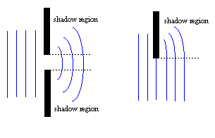
waves, for example spread out after they go through a narrow aperture, or bend into the 'shadow' region
behind an obstacle.

The Huygens-Fresnel Principle
In 1609 Christian Huygens proposed that in order to predict how a wavefront will propagate:
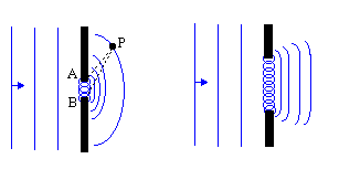
Every point on a propagating wavefront serves as the source of spherical secondary wavelets, such that the wavefront at a later time is the envelope of these wavefronts.This principle was extended by Fresnel to take into account the wavelength of the waves. The Huygens- Fresnel principle states:
Every unobstructed point of a wavefront is a source of spherical secondary wavelets with the same
frequency as that of the primary wave. The amplitude of the resultant wave at any forward point is the
superposition of these wavelets (considering their amplitudes and relative phases). The application of this
principle is to waves near an aperture is shown in .

What all this means is that an analysis of diffraction effects can be performed by treating the aperture as filled with an infinite number of point-sized oscillators each producing spherical wavelets that interfere with each other to produce a diffraction pattern. We can imagine this in the case of light as the electric field vibrating the electrons in the obstruction. Using Maxwell's equations we find that the field due to the oscillation of the electrons exactly cancels the field due to the light wave in the region beyond the obstruction. If an aperture is removed from the obstruction, however, the electron-oscillators are removed along with it and hence light will propagate beyond the screen. Up to a sign, it is as if the source and screen had been removed leaving on the oscillators distributed over the aperture. Thus, up to a sign, we can consider the pattern created by the aperture as the same as that created by point-source oscillators distributed over the aperture.
Single Slit Diffraction
When a pattern created by an aperture is viewed on a nearby screen we see a clearly recognizable image of the aperture with accompanying fringes. This is called Frenel or near-field diffraction. At larger distances the pattern spreads out much more, such that the image of the aperture is likely to be unrecognizable; in this region, moving the screen changes only the size of the pattern and not the shape. This is called the far-field or Fraunhoffer diffraction. We will only treat the latter in the case of a single slit. Fraunhoffer diffraction is the (linear) limit in which the incoming and outgoing wavefronts are essentially planar. This usually occurs when L, the distance between the aperture and the screen is L > d2/λ, where d is the width of the aperture. The Fraunhoffer condition can be achieved in practice by placing a lens with its focus at the source between the source and the aperture and another lens between the aperture and the screen, with its focus at the screen.
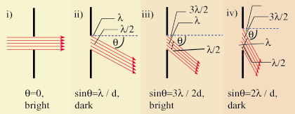
Consider a single slit of width d. Assume that plane, monochromatic waves fall on the slit. Because the
screen on which the diffraction pattern is to be observed is far away (compared to the width of the slit),
light rays heading for any point can be considered essentially parallel. Clearly, all rays heading towards the
center of the screen will arrive in phase, and produce a maximum. Consider waves heading off at some
angle θm such that the path difference between the point source at A and the point source at B is
λ.

 , where d is the
width of the slit. Thus the minima occur at angles:
sinθm =  |
At m = 0 there is a maximum. A full analysis of the situation reveals that the irradiance as a function of the angular displacement, θ is:
I(θ) = I0   |
where I0 is the irradiance of the central maximum. This result is obtained by computing the contribution of the electric field to a point P on a distance screen and integrating over the slit. When L the distance to the screen is much greater than d the distance between the slits, the distance to any point P is essentially the same (L). Thus if each emitter (of unit width) has a source strength ε, ε/L is constant for all points on the slit. If the slit is oriented in the x direction a differential segment dx contributes to the field at P an amount:
dE =  sin(σt - kr)dx sin(σt - kr)dx |
r is the distance from a point on the slit to P and can be approximated by r
 L - x sinθ. We can now
perform the integration to find the electric field at P:
E =   sin[σt - k(L - x sinθ)]dx sin[σt - k(L - x sinθ)]dx |
So:
E =   sin(σt - kL) sin(σt - kL) |
The irradiance is the time average of the electric field squared so recalling that the average of sin2(σt) we find that:
I =        |
which is the same as the result above if we recall k =
 . It also follows from this calculation that
the maxima occur not half way between the minima as might be expected but at the points correponding to the
solution of the transcendental equation:
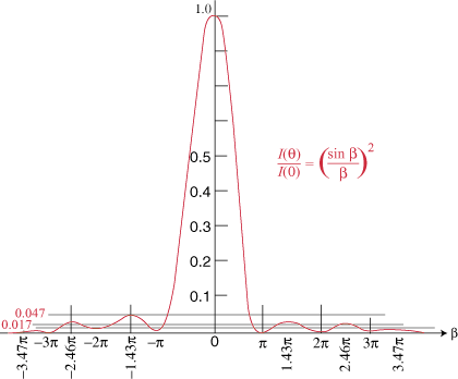
| tan(Πd /λ) = Πd /λ |
These are at ±1.4303Π, ±2.4590Π, ±3.4707Π, etc. A plot of irradiance versus position is shown in .

The analysis by integration over the slits can easily be extended to double or multiple slit systems, or even rectangular or
circular apertures. In the double slit case, the diffraction pattern resembles the double slit interference pattern we found for
Young's experiment, modulated by the envelope of a diffraction pattern similar to the single slit.


 payment page


